From 3D Printed Prototype Molds to Production Tooling: How to Reduce Flash
3D printed prototype molds are useful for early product development. They help engineering teams test geometry, produce first samples, and learn quickly before committing to production tooling.
But once a prototype process begins supplying customer samples or small-batch orders, the expectations change. A mold that was good enough for learning may not be stable enough for repeatable production.
A common example is flash. Teams using FDM or SLA prototype molds may find that the part shape is acceptable, but the edges need hand trimming after every cycle. At first, trimming with a knife may seem manageable. Over time, it becomes slow, inconsistent, and risky, especially if the part is used in medical, packaging, cap, closure, cosmetic, or sealing applications.
Quick answer: 3D printed prototype molds often create flash because the parting line, mold rigidity, clamping stability, and surface accuracy are limited. Overflow wells and tear-trim features can help manage excess material, but they cannot replace accurate production tooling.
Why Prototype Molds Often Create Flash
Flash is not only extra material around a molded part. It is usually a sign that the mold is not controlling pressure, shut-off, venting, or alignment well enough.
In prototype molds, flash commonly comes from:
- Poor parting-line fit
- Limited flatness between mold halves
- Uneven clamping pressure
- Low mold rigidity under pressure
- Uncontrolled vent depth or vent location
- Material deformation during repeated cycles
- Wear on mating surfaces
- Manual assembly or manual clamping variation
These problems are especially visible when the molded material flows easily or when the part has thin edges, sealing features, or cosmetic surfaces. Even a small gap at the parting line can create a thin film of flash that must be removed later.
That is why flash control should start with tooling stability, not post-processing.
Why Flash Becomes a Production Risk
In early prototyping, a little flash may be acceptable. A designer may trim several samples, inspect the part, and continue testing. That is normal during development.
The problem begins when trimming becomes part of the production workflow.
| Flash Issue | Production Risk |
|---|---|
| Knife trimming | Slow labor process and possible cut marks |
| Inconsistent flash thickness | Difficult and unpredictable deflashing |
| Parting-line witness marks | Visible surface defects |
| Flash near sealing areas | Possible leakage or assembly failure |
| Flash on medical components | Higher rejection risk and validation concerns |
| Variation between cavities | Poor repeatability when production scales |
For a one-off sample, trimming may be acceptable. For customer delivery, medical validation, packaging approval, or multi-cavity production, flash becomes a tooling and process risk.
Why 3D Printed Molds Struggle With Parting-Line Control
FDM and SLA molds can shorten development time, but they do not behave like production-grade metal tooling.
FDM molds are especially limited because layer lines, local surface variation, and dimensional drift make it difficult to create a clean parting-line shut-off. SLA molds can improve surface resolution, but they still have limitations in rigidity, wear resistance, and thermal stability.
Common limitations include:
- Layer lines that prevent full contact between mold halves
- Limited flatness across the parting surface
- Lower stiffness compared with aluminum or steel tooling
- Heat sensitivity during repeated molding cycles
- Surface wear that becomes worse over time
- Manual clamping variation from cycle to cycle
- Lower dimensional accuracy in thin flash-control features
This does not make 3D printed molds a poor choice. They are often the right tool for concept testing and early sample work. The mistake is expecting them to deliver the same flash control, surface finish, and repeatability as production tooling.
Can Overflow Wells or Tear-Trim Features Help?
Overflow wells, gutters, and tear-trim features can be useful when they are designed correctly. Their purpose is to move excess material into a controlled area, making it easier to remove after molding.
They can help by:
- Moving flash away from functional surfaces
- Giving operators a cleaner area to grip and remove excess material
- Reducing random knife trimming around the part edge
- Protecting the main part surface from trimming damage
- Improving consistency in a secondary trimming operation
However, these features have limits. They cannot fully correct poor parting-line fit, weak clamping, mold deformation, uncontrolled venting, or low-precision mating faces.
A tear-trim feature may reduce manual damage, but it may still leave a witness line. For medical parts, sealing features, closure parts, or cosmetic packaging, that witness line may still be unacceptable.
The practical conclusion is simple: design features can make flash easier to manage, but accurate tooling is what reduces flash at the source.
When to Move From Prototype Tooling to Production Tooling
Prototype tooling is for learning. Production tooling is for repeatability.
A project may be ready to move beyond 3D printed prototype molds when:
- Manual trimming takes too much time
- Flash affects customer approval
- Knife trimming leaves visible marks
- The part is already being sold in small batches
- Production demand is increasing
- ISO, medical, or customer validation is planned
- Multiple cavities will be needed
- Dimensional repeatability becomes more important than design flexibility
- The same part must be produced consistently over time
This is the stage where tooling risk becomes business risk. If the mold cannot control the parting line, the production team may spend more money correcting parts than it would have spent improving the tooling strategy earlier.
What Production Tooling Should Control
A production mold should do more than create the part shape. It should control the molding conditions that make the part repeatable.
For flash-sensitive components, a production tooling review should include:
- Parting-line fit and shut-off quality
- Vent geometry and vent location
- Clamp force distribution
- Cavity and core alignment
- Insert flatness and rigidity
- Material flow path
- Surface finish requirements
- Datum relationships
- Replacement insert strategy
- Inspection and measurement requirements
Parting-line fit, venting, and clamp force are usually the first areas to review. If one of those areas is unstable, flash often returns even after process adjustments.
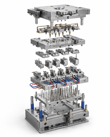
This is where plastic injection molding tooling needs to be planned around the real production environment, not only around the prototype geometry.
Why Removable Inserts Help During Scale-Up
One practical strategy during prototype-to-production development is to use a mold base with removable inserts. This gives the project more flexibility while still moving toward a production-ready tool.
Removable inserts can help:
- Reduce redesign cost
- Isolate cavity-specific problems
- Support design changes after early trials
- Simplify repair and maintenance
- Reduce full mold downtime
- Improve replacement part control
- Support future multi-cavity development
For medical and packaging projects, insert accuracy often determines whether the final molded product remains stable. The mold base provides the platform, but the insert controls the cavity detail, shut-off quality, thread geometry, sealing area, and parting-line behavior.
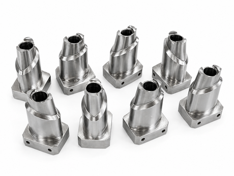
That is why high-quality precision mold components are important when a project moves from prototype samples to production tooling.
What Buyers Should Prepare Before DFM Review
A good DFM review is easier when the tooling supplier receives clear information early. For flash problems, photos and real sample details are especially useful because they show where the mold is failing to control the material.
Before requesting production tooling support, buyers should prepare:
- 3D model
- 2D drawing
- Material type
- Part size and wall thickness
- Target annual volume
- Current prototype photos
- Flash location photos
- Current trimming method
- Acceptable and unacceptable flash areas
- Surface finish requirements
- Sealing or assembly functions
- Medical, packaging, or validation requirements
- Expected cavity number
- Inspection requirements
For complex inserts, shut-off areas, thread features, or small sealing details, buyers may also need custom machined mold parts rather than a general-purpose prototype tool.
How SENLAN Supports Production Mold Stability
SENLAN Precision supports custom mold components and injection mold solutions for projects that require stable production performance. Typical applications include medical consumables, bottle caps, closures, skincare packaging, cosmetic packaging, refill packaging, plastic spout closures, and multi-cavity injection mold projects.
For projects moving from prototype tooling to production tooling, the key is to review risk before the mold is built. That review may include parting-line location, insert accuracy, venting strategy, cooling considerations, critical shut-off areas, replacement component control, and inspection planning.
Depending on the product, buyers may need application-specific tooling support such as medical mold components, cap mold components, or cosmetic packaging mold components.
A stable molded product is not created by mold steel alone. It depends on part design, tooling structure, insert accuracy, process planning, and inspection control working together.
Practical Checklist Before Production
Before approving production tooling, review the project from three angles: product design, tooling design, and production planning.
Product Design
- Where is the parting line located?
- Is flash allowed in that area?
- Does the part have sealing, medical-contact, or cosmetic surfaces?
- Can a tear-trim or overflow feature be added safely?
- Will trimming leave unacceptable marks?
Tooling Design
- Is parting-line fit controlled?
- Are vents properly designed?
- Is clamp force evenly distributed?
- Are inserts rigid and stable?
- Are critical shut-off areas polished, ground, or fitted correctly?
- Are removable inserts needed for future changes?
Production Planning
- What is the expected annual volume?
- Is manual trimming still acceptable?
- Is there an ISO, validation, or customer approval requirement?
- Will multiple cavities be needed?
- What inspection report should be provided?
- How will replacement inserts be controlled?
This checklist helps turn a prototype problem into a production tooling decision. It also helps buyers avoid approving a tool that still depends too heavily on manual repair.
FAQ
Why do 3D printed prototype molds create more flash?
3D printed prototype molds often create more flash because their mating faces, flatness, rigidity, and clamping stability are limited compared with production metal tooling. FDM layer lines and material deformation can create small gaps where material escapes.
Can overflow wells eliminate flash?
Overflow wells can guide excess material and make flash easier to remove, but they usually cannot eliminate flash if the parting line, venting, clamping, or mold accuracy is unstable.
What is a tear-trim design?
A tear-trim design creates a controlled thin flash area that can be removed after molding. It can reduce manual knife trimming, but it still requires accurate tooling and may leave a witness line.
When should a prototype mold be replaced by metal tooling?
A prototype mold should be replaced by production tooling when trimming time becomes too high, flash affects part quality, demand increases, validation is required, or repeatability becomes more important than prototype flexibility.
How does parting-line fit affect flash?
If the parting line does not close tightly and evenly, material can escape through small gaps. This creates flash, especially in low-viscosity or flash-sensitive molding processes.
What should buyers provide before production tooling?
Buyers should provide 3D files, 2D drawings, material information, part samples or photos, flash problem areas, expected production volume, surface requirements, functional areas, and inspection expectations.
Final Thoughts
3D printed prototype molds are valuable for product development, but they cannot solve every production problem.
When flash, manual trimming, part damage, and repeatability problems become recurring issues, the project should move toward properly designed production tooling. Overflow wells, gutters, and tear-trim features may improve flash removal, but they cannot replace accurate parting-line fit, stable inserts, proper venting, controlled clamping, and production-grade machining.
For medical and packaging projects, tooling stability is not just a manufacturing detail. It affects product quality, customer approval, validation planning, and long-term production reliability.
Prototype tooling helps prove the idea. Production tooling helps prove the process.
Need Help Moving From Prototype Tooling to Production Mold Components?
If your prototype mold is creating flash, trimming time, unstable fit, or repeatability issues, early tooling review can reduce production risk.
Send your 3D model, 2D drawing, material requirement, prototype photos, flash location photos, and target production volume. SENLAN can help review parting-line risk, insert accuracy, venting, and production tooling strategy for medical, packaging, cap, closure, cosmetic packaging, and plastic spout closure projects.
contact SENLAN to discuss your production tooling requirements.