
Views: 0 Author: Site Editor Publish Time: 2026-06-12 Origin: Site


Tooling represents the most capital-intensive phase of any insert molding project. Poor upfront design quickly leads to recurring operational losses. You might face issues like flash, severe insert displacement, or unacceptably high scrap rates. It is time to shift our focus from basic concept definitions to actual execution realities. Evaluating tool design requires us to scrutinize structural limits. We must also analyze thermal dynamics and strict material compatibility. Without these thorough checks, molded components will fail early.
In this guide, we outline the exact criteria engineering and procurement teams must evaluate. You will learn how to ensure your tooling investments yield predictable and scalable outcomes. We will explore ways to maintain compliant production cycles across high-volume runs. By understanding how to hold parts securely and map thermal shrinkage, you build robust manufacturing ecosystems. Proper planning prevents expensive tool rework later and safeguards your operational efficiency.
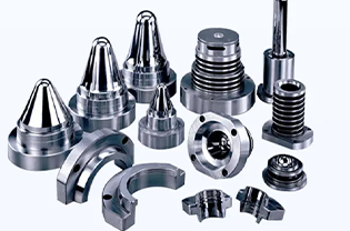
Precision in mold cavity inserts directly impacts cycle times, defect rates, and total tooling lifespan.
Secure insert fixation (mechanical, magnetic, or vacuum) is non-negotiable for preventing structural failures and mold damage.
Design for Manufacturing (DFM) must address thermal shrinkage, wall thickness, and draft angles to ensure structural integrity around the insert.
Selecting a manufacturing partner requires evaluating their capability to manage high-compliance tolerances and provide transparent, data-backed tooling warranties.
Inadequate tool design carries severe financial risks that extend far beyond initial manufacturing expenses. When engineers miscalculate tolerances, they invite accelerated tool wear and critical insert misalignment. These failures cause machine downtime and force costly mold rework. Production stops completely when an improperly seated insert damages the mold core. The ensuing delays disrupt supply chains and erode your expected return on investment.
Evaluating the true value of a tool means looking closely at the cost versus lifespan matrix. Prototype or low-volume aluminum tooling offers quick turnaround times. However, aluminum breaks down quickly under high-volume, abrasive production runs. Conversely, hardened steel tools handle aggressive resins and tight tolerances over millions of cycles. Understanding this balance helps you choose the right material for your project scale.
Tooling Material | Best Use Case | Durability & Lifespan | Abrasion Resistance |
|---|---|---|---|
Aluminum | Prototypes / Low Volume | Short (Under 10,000 cycles) | Low |
P20 Steel | Medium Volume | Moderate (Up to 500,000 cycles) | Medium |
H13 Hardened Steel | High Volume / Harsh Resins | Long (1 Million+ cycles) | High |
A successful tooling investment relies on specific operational metrics rather than the lowest initial quote. We define success by cycle time efficiency, repeatable tolerance adherence, and minimized maintenance downtime. If a tool runs smoothly without constant technician intervention, it provides true value. Frequent stops to clean flash or fix short shots destroy profitability margins.
Risk mitigation requires proactive engineering. Teams must utilize predictive flow analysis before cutting any metal. This software simulates how molten plastic fills the cavity and interacts with the placed components. Rigorous CNC machining of Mold Cavity Inserts ensures a perfect fit. Precision prevents resin from leaking past the insert, which eliminates flash and reduces component rejection rates.
Insert displacement during the high-pressure injection phase remains a massive technical challenge. Molten plastic enters the mold cavity at immense velocity and pressure. If the pre-placed component shifts even a fraction of a millimeter, you risk catastrophic mold failure. Displaced inserts crush against the steel tool, destroying both the part and the expensive cavity. Resolving this requires engineered fixation solutions.
Evaluating fixation mechanisms depends heavily on the geometry and material of the component you want to mold around. Engineers must match the holding method to the specific physical properties of the insert.
Mechanical Clamping: This method works best for standard geometries where physical pins or slides hold the component. You must carefully evaluate the clamping force. Too much pressure risks crushing delicate or thin-walled inserts before the plastic even enters.
Magnetic Fixation: Magnetic holds are ideal for ferrous inserts. They eliminate the need for complex moving parts within the tool. However, you must assess limitations regarding temperature degradation. Magnets lose their attractive force as tool temperatures rise during continuous production.
Vacuum Draw: Fragile or non-magnetic components often require vacuum fixation. The tool pulls a vacuum through tiny channels to hold the piece firmly against the cavity wall. You must evaluate the added complexity of tool vacuum systems, as they require meticulous maintenance to prevent clogging.
Design considerations must account for the natural variation found in pre-manufactured components. Inserts stamped or machined by third-party suppliers arrive with their own dimensional tolerances. You should require transparent tolerance documentation from your vendors regarding insert placement clearance. If the pocket in the Mold Cavity Inserts is too tight, the robot cannot load the part. If it is too loose, the injection pressure will wash the insert away.
Design for Manufacturing (DFM) requirements map directly to part durability and failure prevention. When engineers follow strict DFM rules, they eliminate weaknesses in the final molded product. We look closely at how the injected polymer bonds and cures around the rigid internal component. Every radius, wall, and gate location changes the physical outcome of the part.
Managing shrinkage and internal stress requires deep knowledge of material science. Metal inserts and polymer resins possess vastly different coefficients of thermal expansion (CTE). As the plastic cools, it shrinks significantly, while the metal remains relatively static. This CTE mismatch creates severe hoop stress around circular inserts, often leading to immediate or delayed cracking. Tool design dictates cooling rates. Proper placement of conformal cooling channels ensures uniform temperature drops, which relieves internal stress and prevents part failure.
You must establish baseline rules for the minimum plastic thickness surrounding any internal component. If the plastic wall is too thin, the weld lines where the flow fronts meet will lack structural strength. Conversely, excessively thick walls cause differential cooling. This leads to surface sink marks and internal voids.
Maintain a minimum plastic wall thickness equal to one-sixth of the insert diameter.
Ensure uniform wall thickness around the entire circumference to balance shrinkage forces.
Use generous radii at the base of mounting bosses to eliminate sharp stress concentrators.
Proper draft angles and ejection strategies ensure smooth part removal. When the cycle ends, the machine must push the completed assembly out of the tool. Insufficient draft angles create severe drag. This resistance stresses the bond between the plastic and the metal component. Outline the necessity of a minimum 1-to-2-degree draft angle on all vertical walls. Place ejector pins carefully so they push against solid structural areas rather than delicate plastic features. This guarantees smooth ejection without compromising component strength.
Scalability in high-compliance sectors demands exceptional rigor. Medical device manufacturing (ISO 13485), automotive components, and aerospace parts tolerate zero margin for error. These industries require fully documented, repeatable processes. A tool designed for a consumer gadget will not survive the validation hurdles of an aerospace project. You must engineer the tool to handle exact volumetric filling and strict dimensional stability over its entire lifecycle.
Material compatibility introduces another layer of complexity. High-temperature and aggressive engineering resins like PEEK, Ultem, or glass-filled nylons destroy standard tool steel quickly. You must evaluate the necessity of specialized mold coatings to combat this wear. Nickel-PTFE or titanium nitride coatings reduce friction and protect the cavity. Furthermore, corrosion-resistant stainless steel is often required when processing flame-retardant polymers that release caustic gases during injection.
Emphasize the absolute need for rigorous IQ/OQ/PQ protocols during the tooling trial phase.
Installation Qualification (IQ): Verifies the mold setup matches the exact engineering specifications.
Operational Qualification (OQ): Tests the processing window to find upper and lower limits for temperature and pressure.
Performance Qualification (PQ): Confirms the tool consistently produces conforming parts at standard production speeds.
Teams must perform a strict trust and evidence check before approving production. Never accept verbal guarantees of precision from a vendor. Advise your procurement and engineering teams to demand documented historical tolerance data. Reviewing First Article Inspection (FAI) reports and capability indices (Cpk) proves the Mold Cavity Inserts perform correctly under real-world pressures. Data-backed evidence is the only metric that matters in compliance-heavy industries.
Selecting the right manufacturing partner determines the long-term success of your production run. Vendor red flags often appear early in the quoting process. Warn your teams against partners who skip predictive mold-flow analysis to save time. If they rely purely on guesswork rather than software simulation, they will likely face excessive rework later. Another major red flag is a lack of in-house tooling maintenance. Vendors who ship broken tools out for repair cause massive supply chain delays. Finally, reject partners who offer generic DFM feedback instead of customized, part-specific engineering reviews.
You should require a strict set of capabilities before signing any contracts. Evaluate their facility infrastructure and their approach to transparent business practices.
In-house precision machining: They must possess advanced CNC and wire EDM capabilities specifically for machining complex cavity geometries. Relying on subcontractors for critical tool components introduces unacceptable risks.
Transparent cost breakdowns: Demand itemized quotes. They should clearly distinguish the costs of the main tool base, the custom cavities, the specific fixation mechanisms, and ongoing preventative maintenance.
Proven lifecycle management: Establish clear terms regarding tool ownership. Secure written commitments on guaranteed shot counts and mandated preventative maintenance schedules.
We recommend initiating the evaluation process by starting small. Request a comprehensive DFM review on a pilot CAD model first. This tests the vendor's engineering rigor and communication style before you commit to a major tooling contract. A capable partner will return your CAD file with detailed markups, structural suggestions, and a clear plan for managing insert tolerances.
Successful insert molding relies entirely on meticulous tool engineering. The design, precision, and fixation of the internal cavity components dictate the outcome of the entire production run. When you ignore thermal dynamics or apply inadequate clamping forces, you invite rapid tool failure and high scrap rates. Precision engineering prevents these costly disruptions and builds a scalable manufacturing process.
We urge decision-makers to prioritize upfront DFM collaboration. Investing in robust tooling materials and predictive flow analysis yields far better returns than chasing short-term upfront savings. A poorly built tool will drain your resources through constant maintenance, while a rigorously engineered tool runs seamlessly for millions of cycles.
Take proactive steps today to secure your next manufacturing project. Submit your CAD files to a qualified partner for an initial engineering review. Contact a specialized technical team to discuss custom tooling architecture, validate your material selections, and ensure your next launch remains entirely defect-free.
A: Custom inserts increase upfront CNC and EDM machining expenses. However, they drastically reduce per-part assembly costs downstream. By molding the component directly into the plastic, you eliminate secondary gluing or fastening operations. A precise cavity design also minimizes long-term scrap rates, ensuring higher overall profitability over the tool's lifespan.
A: Realistic engineering baselines typically range from +/- 0.001 to 0.002 inches, depending on the application's strictness. While some high-compliance medical tools require tighter limits, pushing tolerances beyond standard baselines exponentially increases tooling complexity and upfront manufacturing costs.
A: Standard industry timelines usually span 4 to 8 weeks. This timeline covers initial DFM, flow analysis, machining, and First Article testing. Projects requiring complex fixation mechanisms, such as integrated vacuum systems, or tools cut from heavily hardened steel, naturally extend these lead times.
A: While minor core or cavity modifications are sometimes possible, retrofitting a standard mold for insert fixation is generally discouraged. Adding robotic loading clearances and structural clamping to an older tool is riskier and less structurally sound than engineering a purpose-built tool from scratch.


