
Views: 0 Author: Site Editor Publish Time: 2026-06-03 Origin: Site


Ejecting complex injection-molded parts poses a unique engineering hurdle. Hollow bosses, cylindrical features, and deep cores often resist clean removal from the mold. These precise geometries easily suffer cosmetic damage or structural deformation during standard ejection sequences.
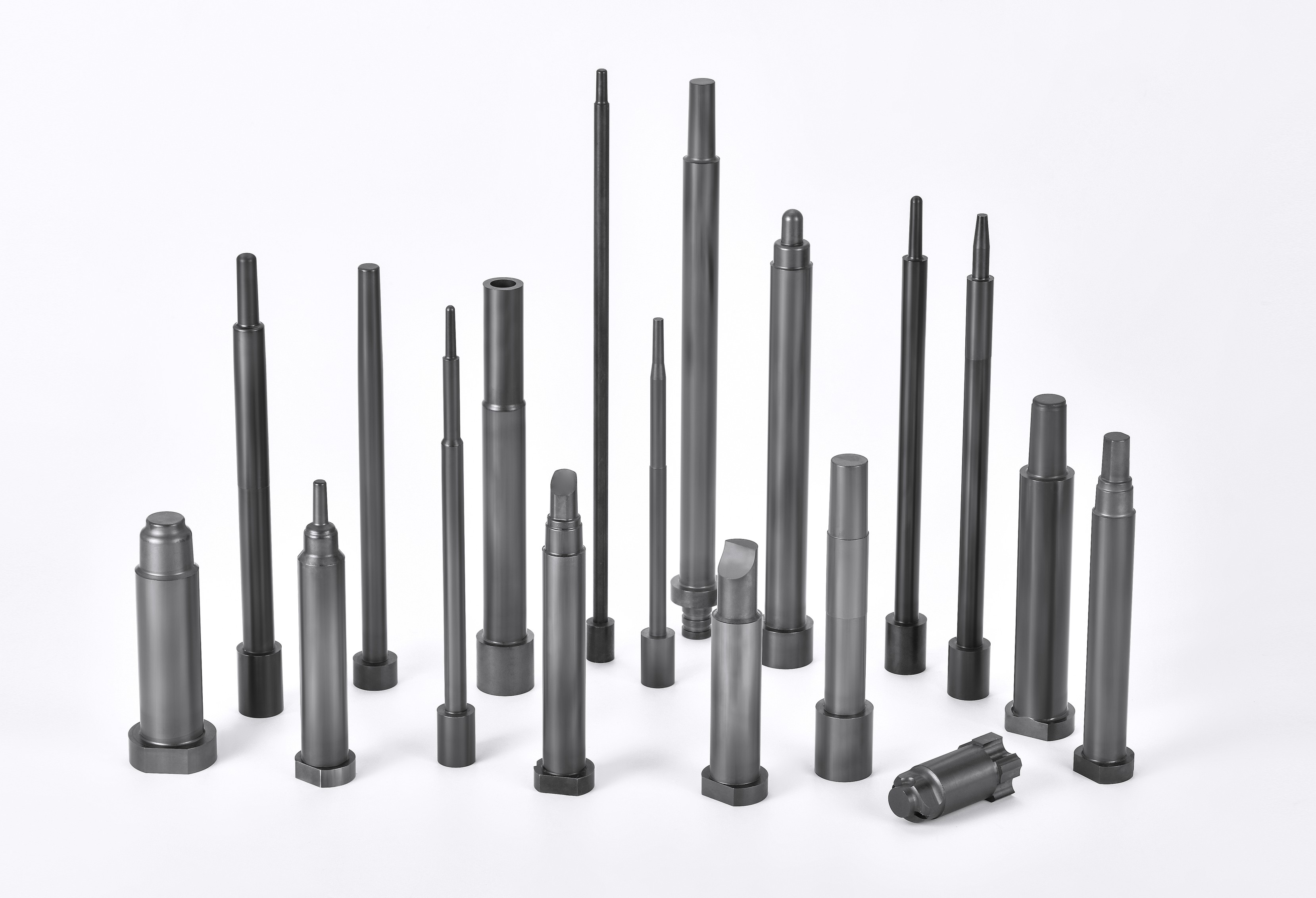
When standard pins push against thin walls, they frequently cause stress whitening or punch completely through the plastic. Ejector Sleeves provide a purpose-built solution. They deliver uniform ejection force entirely around circular profiles to safely release the molded part. By distributing the mechanical load, they preserve the structural integrity of delicate features.
This comprehensive guide breaks down the core mechanics of sleeve ejection systems. You will learn how to select the proper tool steel and specify advanced surface treatments. We will also cover essential procurement criteria to ensure your high-volume tooling operates flawlessly without unexpected maintenance delays.
Ejector sleeves distribute ejection force evenly across circular or hollow features, preventing the pin punch-through or part distortion common with standard ejector pins.
The system requires a precise two-part assembly—an outer sleeve and a stationary inner core pin—demanding strict concentricity tolerances.
Material selection (e.g., SKD61, H13) and surface treatments (nitriding, vacuum hardening) must align with the abrasiveness of the injected resin to prevent premature galling.
Evaluating suppliers should center on their machining tolerances, surface finish capabilities, and custom sizing options to mitigate long-term maintenance risks.
The architecture of an ejection sleeve system relies on tight mechanical synergy. It features two distinct components working together perfectly. First, the tubular ejector sleeve actively moves during the cycle. Second, a central core pin remains completely stationary. To function correctly, engineers must calculate precise clearances. The gap between the inner diameter of the sleeve and the core pin must be tight enough to prevent plastic leakage. Similarly, the outer diameter needs accurate clearance within the mold plate to ensure smooth sliding.
Standard mold bases integrate specific ejector retainer plates to hold the sleeve base firmly. The core pin typically anchors securely into a separate bottom clamping plate. This separation allows independent movement during the ejection phase.
The working principle activates during the mold opening phase. The sequence follows these exact steps:
The injection molding machine completes the cooling phase.
The mold opens, separating the core and cavity halves.
The machine's hydraulic ejector plate pushes the tubular sleeve forward.
The central core pin stays rigidly anchored in its base plate.
The advancing sleeve pushes against the base of the molded feature.
This mechanism strips the molded part off the stationary core.
This action applies 360-degree uniform pressure. It safely pushes the plastic off the core without localized stress. Success heavily relies on precise alignment. If the components lack concentricity, they will scrape against each other. Friction generates excessive heat and wears down the metal. Proper implementation guarantees mold integrity and secures repeatable cycle times for the life of the tool. Toolmakers must achieve an exacting fit to prevent premature mechanical wear.
Standard ejector pins often fail when ejecting tubular geometries. Pushing a solid pin against a thin hollow boss concentrates force in one tiny area. This concentration leads to severe part defects. You might observe stress whitening, warping, or even pins puncturing right through the plastic. Stress whitening occurs because the polymer chains stretch beyond their yield point. This visual defect renders the part unacceptable for consumer applications.
To solve this, designers specify Ejector Sleeves for specific geometric challenges. You should use them for parts containing deep cylindrical cavities. They are equally vital for hollow screw bosses. Additionally, they work perfectly for applications demanding completely flush cosmetic surfaces. By distributing the load evenly around the perimeter, they eliminate ugly pin marks on the final product. Your quality control team will immediately notice the improvement in cosmetic consistency.
Conversely, standard ejector pins still hold value. You should rely on them for flat, solid surfaces possessing high structural integrity. Standard pins cost less and require simpler machining. If your part features undercuts, neither standard pins nor straight sleeves will work. Instead, those complex geometries require angled lifters or intricate slider mechanisms to release the trapped plastic.
Feature | Standard Ejector Pins | Ejector Sleeves |
|---|---|---|
Target Application | Flat, solid, structurally sound surfaces | Hollow bosses, deep cores, cylindrical features |
Force Distribution | Highly localized point load | 360-degree uniform perimeter load |
Machining Complexity | Low (Straight cylindrical boring) | High (Requires strict concentricity matching) |
Risk of Part Distortion | High on thin-walled tubular parts | Extremely low across all circular geometries |
While sleeve setups require higher upfront tooling investments, they drastically improve production outcomes. They demand much stricter machining tolerances than basic pins. The toolmaker must bore precise holes and align multiple plates flawlessly. However, they significantly reduce scrap rates. By preventing part distortion, they eliminate cycle interruptions when molding complex geometries. This reliability justifies the initial engineering expense.
Choosing the right tool steel dictates the lifespan of your ejection system. You must balance core toughness with surface hardness. The industry relies heavily on Hot-Work Tool Steels. Materials like H13 and SKD61 dominate most applications. They offer high tensile strength and excellent thermal fatigue resistance. Thermal fatigue happens when metals rapidly heat and cool, eventually causing micro-cracks. H13 and SKD61 resist this cracking exceptionally well.
For high-precision or high-wear environments, High-Speed Steels step in. SKH51 provides superior performance when millions of cycles are expected. It maintains its hardness even at elevated operating temperatures. This stability ensures the sleeve does not deform under constant mechanical pressure.
Surface treatments determine how well the sleeve withstands abrasive resins. Nitrided components feature a hardened outer layer reaching HV 900 or higher. The nitriding process diffuses nitrogen into the surface of the steel. This incredibly hard shell covers a tough, ductile core. Nitriding prevents galling and easily withstands harsh materials like glass-filled nylon or carbon-fiber-reinforced polymers.
You must also decide between through-hardened and surface-hardened options. This choice depends on your expected production volume.
Surface-Hardened: Ideal for massive production runs facing abrasive wear. The hard shell resists scratches, while the soft core absorbs mechanical shocks.
Through-Hardened: Serves well for prototyping or lower-volume, non-abrasive applications. They cost less to manufacture but may snap under extreme lateral stress.
One critical evaluation dimension involves thermal expansion. The sleeve material must match the coefficient of thermal expansion of the surrounding mold plates. As the mold heats up during production, mismatched metals expand at different rates. If they expand differently, the sleeve will bind or seize inside the tool. Engineers must calculate these expansion rates during the initial mold design phase to prevent catastrophic tooling failure.
Even well-designed tools encounter operational issues over time. Understanding common implementation risks helps you prevent costly downtime. We categorize these risks into three primary areas: friction, clearance, and vacuum forces. Properly diagnosing these issues early will save your tooling from permanent damage.
First, galling and seizing frequently destroy moving components. This failure stems from insufficient lubrication or a poor surface finish. Microscopic high points on the metal grind against each other under high pressure. Thermal expansion mismatch between the sleeve and the core pin also causes seizing. To solve this, you must specify dissimilar hardness levels. Make the sleeve and the core pin different hardnesses. For example, use a harder pin and a slightly softer sleeve. Furthermore, implement proper mold venting to manage heat buildup and let trapped gases escape.
Second, flash formation ruins part aesthetics. Flash occurs when plastic leaks into the clearance gap between the moving parts. Excessive clearance usually results from prolonged wear or poor initial machining tolerances. Establish routine maintenance schedules to check for wear using precision gauges. More importantly, mandate initial supplier tolerances of ±0.005mm or tighter. The exact tolerance depends heavily on the resin's viscosity. Low-viscosity materials like nylon require much tighter clearances than thick materials like polycarbonate.
Third, parts sometimes stick stubbornly to the core. This happens because the ejection stroke creates a powerful vacuum inside the part cavity. As the plastic pulls away, air cannot enter fast enough to equalize the pressure. To fix this, evaluate the need for air poppets. Air poppets inject compressed air to break the seal. You can also apply specific micro-texturing on the core pin. These modifications break the vacuum seal right as the sleeve pushes forward.
Implementation Risk | Primary Cause | Recommended Solution |
|---|---|---|
Galling and Seizing | Insufficient lubrication; Thermal mismatch | Specify dissimilar hardness; Improve mold venting |
Flash Formation | Excessive clearance from wear or poor tolerance | Mandate ±0.005mm tolerance; Implement maintenance schedule |
Part Sticking on Core | Vacuum creation during ejection stroke | Integrate air poppets; Apply core pin micro-texturing |
Sourcing high-quality mold components demands strict supplier evaluation. You cannot afford to buy substandard parts for critical ejection systems. Slight deviations in concentricity lead to immediate, catastrophic tooling failure. If the inner hole is slightly off-center, the wall thickness varies. The thin side will wear out quickly and break under pressure. Manufacturers must provide detailed inspection reports. These documents must validate exact concentricity across the entire length of the component using coordinate measuring machines (CMM).
Next, assess their customization capabilities. Off-the-shelf catalog sizes rarely fit specialized, complex molds perfectly. Determine if the manufacturer can reliably produce stepped sleeves. Stepped designs feature varying outer diameters to add strength to long, slender parts. Ask about their capacity for custom lengths and non-standard inner diameters. A versatile supplier adapts to your mold design, rather than forcing you to adapt to their generic catalog.
Quality assurance and traceability act as your safety net. Look for current ISO certifications proving their commitment to quality management. Demand official material certificates for every batch. These certificates guarantee the tool steel specified matches the actual material delivered. Counterfeit or low-grade steel will fail prematurely under injection pressures, costing you thousands in repairs and lost production time.
When shortlisting suppliers, employ a logical testing sequence. Recommend requesting pilot samples before committing to large-scale tooling orders. Test these samples in a prototype mold to verify performance. If possible, audit the supplier's facility in person. Inspect their grinding and lapping machinery capabilities firsthand. High-end cylindrical grinding machines and skilled operators are absolutely essential for achieving the required surface finishes and micro-tolerances.
Upgrading your mold design yields significant production benefits. These specialized ejection systems are critical investments. They enable the precise, damage-free ejection of tubular and boss-heavy injection-molded parts. By distributing force evenly, they protect your product's structural integrity and cosmetic finish. They eliminate the high scrap rates associated with standard pin push-through and part distortion.
Your engineering and procurement teams should take immediate action. Audit your current mold designs to identify recurring sticking or warping issues. Pinpoint geometries where standard pins consistently fail to release the plastic cleanly. Look for stress marks or whitening on existing production parts. Once identified, consult with high-precision tooling manufacturers to upgrade those problematic ejection systems.
Do not let inadequate ejection mechanisms slow down your manufacturing cycles. Request a technical consultation today. Provide your specific mold drawings to receive a custom quote. Implementing the right components will drastically improve your yield, reduce unexpected downtime, and boost overall operational efficiency.
A: The required clearance depends heavily on the specific resin's viscosity. However, it typically ranges from 0.01mm to 0.02mm. Keeping this gap tight is crucial to prevent molten plastic from leaking into the mechanism and causing flash.
A: Yes, they can handle highly abrasive materials. To survive glass-filled plastics, the components must undergo advanced surface hardening treatments. Options like gas nitriding or titanium coating provide the extreme surface hardness necessary to resist severe abrasive wear.
A: Maintenance intervals depend entirely on your total cycle counts and the resin used. You should establish a strict preventative schedule. Regularly lubricate the moving components and inspect the molded parts for early signs of flash, which indicates wear.
A: Several factors cause catastrophic breakage. The primary culprits include mechanical misalignment and thermal binding from mismatched expansion rates. Additionally, improper core pin sizing or lack of sufficient lubrication will cause the metals to seize and eventually fracture.


