
Views: 0 Author: Site Editor Publish Time: 2026-11-13 Origin: Site


Are secondary assembly costs eating into your production margins? Complex flip-top caps demand a more efficient manufacturing approach. Poor internal tooling designs inevitably cause flash and part defects. This makes achieving perfect steel-to-steel contact inside the cavity an absolute necessity for profitable operations.
Recent industry analyses highlight a massive shift in the packaging sector. Rising labor costs and increasingly stringent hygiene standards are driving a rapid transition toward fully automated, single-step molding processes. Manufacturers are aggressively moving away from traditional two-step molding and secondary assembly. Instead, they favor integrated, hands-free solutions. At the heart of this industry-wide upgrade is the demand for flawless internal mold mechanics. Mastering these mechanics—specifically the shut-off surfaces—is absolutely vital when engineering an In-Mold Closing Cap Injection Mold. Because these advanced tools fold and snap the cap closed before ejection, the mating steel surfaces forming the living hinge and closure mechanisms must be executed with micron-level precision.
In this comprehensive engineering guide, we will explore the foundational physics of shut-off design. We will break down its specific applications in highly automated closure molds, highlight common shop-floor mistakes to avoid, and provide actionable best practices to ensure high-yield, flash-free production.
Defining Complex Features: Internal steel-to-steel contact is essential for creating through-holes, snap-fits, and living hinges. It eliminates the need for complex, maintenance-heavy external cam mechanisms.
Critical for Automation: An automated in-mold closing system relies entirely on perfectly calibrated contact surfaces to form delicate features—like the dispensing orifice—without flashing.
Draft Angles are Mandatory: A minimum draft angle of 3 to 5 degrees is strictly required on all mating surfaces. This prevents steel galling, severe friction, and premature tool degradation.
Precision Prevents Downtime: Avoiding common engineering oversights like inadequate venting, poor spotting, and ignoring thermal expansion will save thousands of dollars in tool maintenance.
To engineer high-volume, defect-free plastic components, understanding the foundational mechanics of internal tooling contact is a strict requirement. This section defines the core physics governing how these critical features operate under extreme manufacturing conditions.
In tooling engineering, a shut-off is defined as the specific internal area where the core and cavity blocks make direct, intentional contact. The primary function of this steel-to-steel mating is to block the flow of highly pressurized molten plastic. While a standard parting line runs along the outer perimeter of the part to separate the mold halves, an internal shut-off creates features strictly within the part boundaries. By preventing polymer from filling specific geometric spaces, these barriers form internal windows, through-holes, and complex undercut geometries.
Plastic processing is governed by extreme physical forces. During the injection phase, molten polymer is blasted into the cavity at pressures frequently exceeding 15,000 PSI. To prevent the tool from blowing apart under this immense pressure, the molding machine applies a massive clamping force. This tonnage is often measured in hundreds or thousands of tons.
Contact surfaces exist squarely at the volatile intersection of these two opposing forces. The steel faces must be machined with exact precision to withstand the injection pressure without separating. Even a microscopic separation of 0.02mm will allow molten plastic to escape. This creates a sharp, unwanted protrusion known as flash. Conversely, if the clamping force is too high and the contact surface area is too small, the steel faces will crush each other. This leads to permanent tooling damage and costly line shutdowns.
From a commercial and maintenance perspective, incorporating bypass designs is highly advantageous. Traditionally, creating undercut features like snap-fits requires sliding cams or side actions. These are mechanical components that move perpendicularly to the primary opening direction of the press. Cams add significant cost to the initial build. They also require continuous lubrication and are highly prone to mechanical failure over millions of cycles.
By utilizing a bypass pass-core, engineers can create these undercut features using only the vertical opening and closing movement of the machine. The core and cavity blocks interlock at a specific draft angle, effectively sealing off the plastic flow to create the snap-fit geometry. This principle drastically reduces tooling complexity, lowers long-term maintenance costs, and significantly improves overall cycle times.
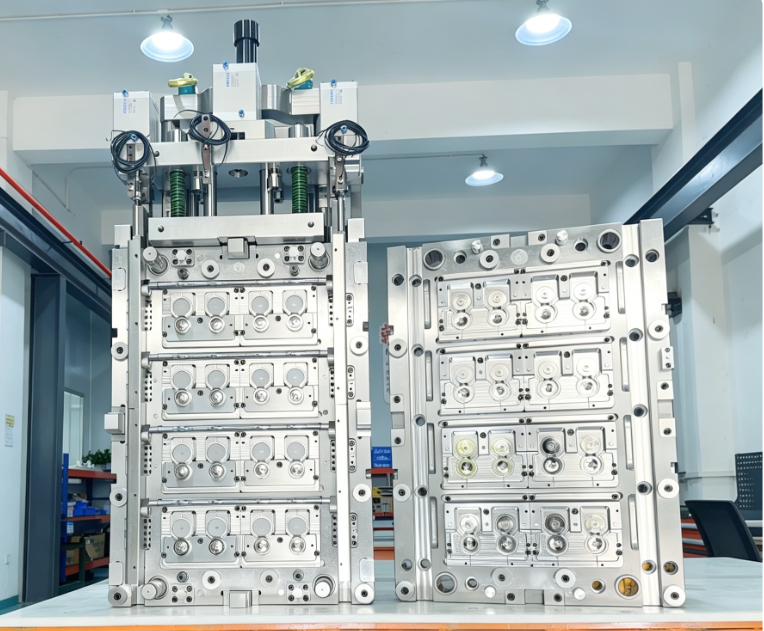
The principles of internal steel contact become exponentially more critical when applied to highly automated packaging solutions. Flip-top caps are ubiquitous on retail shelves, but manufacturing them efficiently requires specialized, high-precision tooling.
A living hinge is a thin, flexible web of plastic connecting the main body of a cap to its lid. It allows the cap to bend repeatedly without tearing. In advanced tooling, forming this hinge requires an ultra-precise steel-to-steel gap. The core and cavity components must come together to leave a uniform space of merely 0.2mm to 0.3mm.
If the alignment shifts by even a few microns, the hinge will suffer from uneven wall thickness. This leads to premature failure or immediate tearing during the first mechanical bend. Furthermore, the surrounding geometry is engineered to direct the polymer flow precisely across the hinge area. This specific flow orientation aligns the polymer molecules perpendicular to the hinge axis, maximizing flexural strength and extending the lifespan of the closure.
Flip-top caps require a clean dispensing orifice for the liquid product and a corresponding sealing pin on the lid to prevent consumer leaks. Mating mold surfaces are utilized to form both of these critical features simultaneously. The core pin forming the orifice must seal perfectly against the opposing cavity block.
Additionally, the cap must remain securely closed during transit and on retail shelves. This is achieved through a precise snap-fit undercut. By utilizing bypass designs, engineers can form the retaining ledge of the snap-fit without relying on complex side actions. This ensures the cap lid snaps securely into the base with a satisfying tactile click, providing absolute consumer confidence in the product seal.
The absolute pinnacle of flip-top manufacturing is the deployment of an automated in-mold closing system. In a standard legacy process, caps are ejected open. They must then be closed by a secondary assembly machine, which consumes valuable factory floor space, energy, and manual labor.
An advanced IMC system utilizes specialized internal kinematics—such as hydraulic closing arms, racks, or sweeping mechanisms. These components fold the cap lid onto the base while the plastic is still warm and pliable on the core, right before the final ejection stroke. High-production setups often feature 24 or 32 cavities running at blistering cycle times of 12 to 15 seconds. For this automated folding to work flawlessly every single cycle, the shut-offs forming the alignment features must be perfect. If flash is present, the mechanical closing arm will jam. The cap halves will misalign, resulting in a crushed product and a halted production line.
To guarantee that a mold functions reliably over a lifespan of millions of cycles, tooling engineers must adhere to strict design guidelines. The following principles are foundational to successful tool execution.
The most critical rule in this type of engineering is the implementation of adequate draft angles. A draft angle is a slight taper applied to the vertical walls of the steel blocks. For mating surfaces, the industry standard is the Rule of 3 Degrees. Engineers mandate that these faces must have a minimum of 3 degrees of draft, though 5 degrees is highly preferred for automated closures.
Without sufficient draft, the opposing steel surfaces will violently scrape against each other during the opening and closing strokes. This friction creates microscopic welds between the steel faces. These welds immediately tear apart as the press moves. This destructive phenomenon, known as galling, destroys the smooth surface finish and rapidly degrades the seal, leading directly to severe flashing.
When a raw block of steel is initially machined using CNC equipment, engineers employ a metal-safe strategy for all critical contact areas. Being metal-safe means intentionally leaving a nominal amount of excess steel—typically 0.05mm to 0.1mm—on the surfaces during the rough and semi-finish milling phases.
Because metal cannot be easily added back once it is cut away, leaving this extra material allows highly skilled toolmakers to manually grind and fit the halves together during final assembly. Toolmakers working with Prussian blue ink rely entirely on this extra margin to hand-grind the final fit. This meticulous process, known as spotting, ensures the core and cavity mate with absolute accuracy. It compensates for any minor machining variances or stack-up tolerances across a multi-cavity tool.
The physical width of the contact land—the actual area of steel touching steel—must be carefully calculated. A common engineering error is making this surface too wide. While it might seem that more contact area equals a better seal, a wide land requires a massive amount of clamping tonnage to crush the two halves perfectly flat. If the machine cannot provide enough tonnage, the tool simply will not close completely.
In contrast, if the land is too narrow, the immense clamping force can cause the steel edge to dent, roll over, or deform over time. The optimal sealing width generally ranges between 3mm and 5mm. This provides a perfect balance between localized sealing pressure and long-term structural integrity.
Mold Feature Size | Recommended Shut-Off Width | Risk of Oversizing | Risk of Undersizing |
|---|---|---|---|
Small — Under 50mm | 2.0mm to 3.0mm | Incomplete mold closing | Edge deformation and rolling |
Medium — 50mm to 150mm | 3.0mm to 5.0mm | Excessive tonnage required | Steel crushing under clamp force |
Large — Over 150mm | 5.0mm to 8.0mm | Poor venting and trapped gas | Accelerated tool wear |
Engineers must calculate the projected area of the internal features to ensure the molding machine's clamping tonnage is sufficient. The projected area is the two-dimensional shadow the feature casts in the direction of the mold opening stroke.
By multiplying this projected area by the internal cavity pressure, engineers determine the separating force. The machine clamping force must exceed this separating force by a safety margin of at least 20 percent. If the clamping force is insufficient, the sheer injection pressure will force the tool open by a few thousandths of an inch. This results in flash across the entire production run and wasted resin.
Precision engineering is the cornerstone of high-volume packaging production. However, even experienced designers can fall victim to specific oversights when detailing complex kinematics. Avoiding these common shop-floor mistakes is essential for maintaining profitability and consistent part quality.
As previously established, draft is essential. Yet, product designers sometimes attempt to use a zero or one-degree taper to maintain a specific aesthetic look on the final plastic part. This is a severe mechanical error. A one-degree draft will almost certainly result in galling within the first few thousand cycles. Repairing galled steel requires halting production, pulling the tool from the press, laser welding new metal onto the damaged area, and re-machining the surface. This process costs thousands of dollars in downtime.
When molten plastic fills a cavity, it rapidly displaces the ambient air that was previously inside. If this air cannot escape, it becomes highly compressed. At the end of the fill phase, which often occurs near a contact barrier, compressed air heats up dramatically. Temperatures can sometimes exceed 1000 degrees Celsius.
If venting channels are not properly designed along the perimeter, this superheated air will literally ignite the surrounding plastic. This causes a severe defect known as a diesel burn, leaving black, charred soot marks on the part. On the factory floor, the distinct smell of burning plastic is a clear indicator of this issue. A diesel burn is particularly disastrous for the delicate living hinge of a flip-top cap, rendering it brittle and useless.
Injection molds are highly dynamic thermal environments. During continuous production cycles, hot plastic continuously transfers heat into the steel blocks. Depending on the cooling channel layout, the core and cavity may operate at vastly different temperatures.
Steel expands as it heats. Standard tool steel has a specific coefficient of thermal expansion. If a tool heats up by 40 degrees Celsius, a 500mm wide block of steel will expand by nearly a quarter of a millimeter. If engineers design tight tolerances based solely on ambient room temperature, the thermal expansion during active production will cause the mating surfaces to seize, bind, or crash. This leads to catastrophic mechanical failure.
Product designers frequently add intricate undercuts, complex logos, or aggressive snap features without consulting tooling engineers. These unnecessary complexities force toolmakers to design convoluted, multi-angled steel surfaces that are incredibly difficult to machine and maintain. Often, a minor modification to the plastic part design—such as changing the angle of a snap-fit by two degrees or moving a hole location slightly—can drastically simplify the internal tooling geometry. A streamlined design reduces the mechanical load on the In-Mold Closing Cap Injection Mold. This translates directly to fewer maintenance requirements and much higher reliability.
Flash is the most prevalent defect associated with internal seal failure. It occurs the moment plastic escapes the intended cavity space. Preventing it requires a combination of high-end manufacturing techniques and optimized material selection.
Achieving a flash-free product begins on the manufacturing floor. High-speed 5-axis CNC milling machines and precise Electrical Discharge Machining are vital for accuracy. They cut the hardened steel to tolerances of plus or minus 0.005mm.
Following the initial machining, seasoned toolmakers perform the critical spotting procedure. They apply a micro-thin layer of Prussian Blue ink to the cavity block and close the tool in a hydraulic spotting press. When opened, the ink transfers to the core wherever there is physical contact. Toolmakers carefully inspect this ink transfer. If the ink is patchy, it indicates high and low spots on the steel. They then use micro-grinding tools to remove the high spots until a uniform, 100 percent ink transfer is achieved. This guarantees a perfect seal under pressure.
Because these surfaces endure millions of high-tonnage impacts, selecting the appropriate tool steel is paramount for long-term success. Soft metals will quickly deform under clamping pressure. Engineering best practices dictate using premium, hardened tool steels for all contact inserts.
For instance, when engineering a high-cavitation closure tool, top-tier manufacturers typically specify S136 stainless steel for the core and cavity inserts. Hardening this steel to HRC 48-50 provides exceptional wear resistance. It also offers excellent corrosion resistance against off-gassing polymers, ensuring the shut-off edges remain sharp and flash-free over a multi-million cycle lifespan.
Tool Steel Grade | Hardness Range | Key Characteristics for Internal Tooling | Typical Application |
|---|---|---|---|
P20 Steel | HRC 28 to 32 | Easy to machine, but far too soft for high-volume wear. | Low-volume prototypes and simple parts. |
H13 Tool Steel | HRC 48 to 52 | Excellent toughness and high thermal fatigue resistance. | High-pressure, high-volume industrial molds. |
S136 Stainless | HRC 48 to 54 | High hardness, superior corrosion resistance, takes a high optical polish. | Premium packaging and automated flip-top closures. |
Designing and building a highly automated tool is a significant capital investment. Sourcing the right equipment is critical to your factory's output. You need a tooling partner who deeply understands complex kinematics, hot runner integration, and high-precision tolerances.
Not all tool shops are equipped to handle the rigorous demands of automated packaging solutions. When evaluating a potential supplier, audit their facility for specific capabilities. Ensure they utilize advanced CNC machining centers capable of micron-level accuracy. Furthermore, verify their quality control department uses Coordinate Measuring Machines to validate that the machined steel matches the 3D CAD data perfectly before assembly begins. Deep experience with complex kinematics—such as rack-and-pinion systems, hydraulic unscrewing, and integrated closing arms—is a mandatory prerequisite.
Building a 24-cavity or 32-cavity automated tool is not a task for novice mold makers. The intricate balance of thermodynamics, fluid dynamics, and mechanical engineering requires specialized expertise. Partnering with industry leaders ensures that your project is handled by seasoned professionals who understand the nuances of shop-floor production.
Expert engineering teams specialize in optimizing complex part geometries to guarantee flash-free production. By leveraging an advanced IMC flip-top cap tooling solution, manufacturers can achieve exceptionally fast cycle times. This eliminates secondary assembly bottlenecks entirely and secures a long-lasting asset that maximizes return on investment.
Flawless internal tooling design is undeniably vital for successful, high-yield molding operations. Implementing proper draft angles, utilizing metal-safe machining practices, and selecting premium hardened steel prevents costly errors and tool degradation. Precision CNC machining and meticulous hand-spotting ensure flash-free, high-quality production runs. For highly automated, high-volume products, investing in perfectly engineered closure tooling yields massive commercial ROI. It completely eliminates the need for secondary assembly machines, drastically reduces scrap rates, and optimizes cycle times down to the second. By adhering to these rigorous engineering principles, manufacturers can achieve superior molding outcomes and maximize their long-term operational success. If you are looking to upgrade your production capabilities, explore the advanced tooling solutions at Senlan Molds to request a design consultation and secure your competitive edge.
Generally, a minimum of 3 degrees is strictly required, but 5 degrees is highly recommended by tooling engineers. This taper prevents steel friction and galling during the opening and closing strokes, ensuring the longevity of the tool and preventing flash.
It is a highly specialized, automated tool used primarily for flip-top packaging. It features internal mechanical systems—such as hydraulic arms or geared racks—that fold and snap the cap closed while the part is still inside the press. This completely eliminates the need for separate, post-molding assembly machines.
Flashing occurs when the steel-to-steel contact is compromised. This can be due to inadequate clamping tonnage from the machine, worn-out or galled steel, excessive injection pressure forcing the tool open, or poor initial spotting where the halves simply do not mate perfectly.
Yes. Damaged surfaces can often be repaired through micro-welding or laser welding to add hardened steel back to the affected area. This is followed by precision re-machining and manually re-spotting the surface to its original dimensions to restore the perfect seal.
Bypass designs are built directly into the vertical movement of the core and cavity. This means there are no moving parts required to create undercuts like snap-fits. This makes the tool cheaper to build, significantly easier to maintain, and much less prone to mechanical failure compared to sliding cams.
During production, the tool steel absorbs heat from the molten plastic and expands. If engineers do not account for this expansion coefficient during the design phase, the mating steel surfaces can bind, gall, or crash when the tool reaches its operating temperature, leading to severe damage.
For high-volume packaging, engineers typically recommend premium stainless steel, such as S136, hardened to HRC 48-50. This provides the necessary toughness to withstand millions of clamping impacts while resisting corrosion from plastic off-gassing, keeping the sealing edges perfectly sharp.


