Views: 0 Author: Site Editor Publish Time: 2026-08-05 Origin: Site


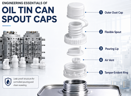
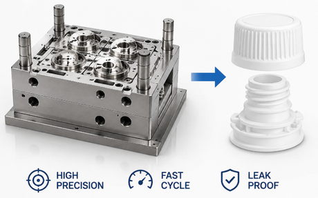
A high-performance spout cap mold is an advanced injection tooling system engineered specifically for manufacturing plastic spouted closures used in flexible pouches, liquid refill packaging, and beverage containers. Designing and manufacturing a spout cap mold demands ultra-precise multi-cavity steel machining, optimized hot runner balancing, conformal cooling circuit placement, and robust automatic unscrewing or mechanical stripping mechanisms to ensure 100% thread integrity, zero flash, superior tamper-evident band formation, and cycle times under eight seconds.
Fundamentals of Spout Cap Mold Engineering
Critical Tooling Components and Material Selection
Hot Runner Systems and Gate Thermal Management
Core Unwinding and Ejection Mechanism Architecture
Conformal Cooling Circuit Design and Rheological Optimization
Precision Manufacturing and CNC Machining Workflows
Quality Control, Testing, and Validation Protocols
Conclusion and Engineering Summary

The foundational engineering of a spout cap mold relies on ultra-precise cavity alignment, robust mold base rigidity, balanced polymer flow paths, and optimized mechanical kinetics to produce identical, defect-free spouted closures across high-cavitation production molds.
When our engineering team approaches the structural formulation of a spout cap mold, we prioritize rigid structural integrity and exact hydraulic balance. Spout caps feature intricate geometric details, including narrow pour spouts, internal thread structures, outer knurling for consumer grip, and delicate tamper-evident ring bridges. Consequently, the spout cap mold must absorb intense injection pressures—often exceeding 1,200 bar—without suffering micro-deflection or thermal distortion across the parting line. Mold plate deflection directly leads to parting line flash, ovality in the cap sealing lip, and thread binding during spout cap mold closure assembly.
From an architectural standpoint, the spout cap mold must incorporate a modular core and cavity design. Rather than machining cavities directly into solid mold plates, individual cavity inserts and core pins are mounted into high-precision pockets. This modularity allows for micro-adjustment of individual spout cap mold cavity alignment, simplifies localized maintenance, and guarantees that any single damaged cavity can be replaced without sacrificing the entire spout cap mold. In high-volume spout cap mold production facilities running 24/7, modularity directly equates to minimized downtime and controlled operational expenditure.
To satisfy the demanding requirements of flexible pouch packaging, our team integrates custom engineering features into every custom spout cap mold for spouted pouches refill packaging. Why do we design the tool with high cavity density and modular spout cap mold core inserts? Because global packaging converters require maximum output per square meter of floor space while maintaining strict dimensional repeatability. In actual factory environments, our clients consistently prioritize spout cap mold thread pitch consistency, torque uniformity, and zero leakage at the pouch spout interface. European clients, in particular, favor fully automated unscrewing systems paired with electrical servo drives to minimize oil contamination in cleanroom manufacturing environments.
Parameter / Specification | Standard Engineering Value | Advanced High-Speed Tooling Specification |
Cavitation Range | 8 Cavities to 32 Cavities | 48 Cavities to 96 Cavities |
Tooling Target Cycle Time | 8.0 to 12.0 seconds | 5.5 to 7.5 seconds |
Core / Cavity Steel Grade | 1.2344 / H13 ESR (HRC 48-52) | S136 ESR / Premium Stainless (HRC 52-56) |
Alignment Guidance Precision | ±0.005 mm Precision Interlocks | Sub-micron Optical Guide Pillars & Tapered Interlocks |
Applicable Polymers | HDPE, PP, LLDPE blends | High-Flow HDPE (MFI 12-25), Random Copolymer PP |
Selecting specialized tool steel and high-wear resistance metallurgy for the spout cap mold core, cavity, unscrewing gears, and guide bushings is vital to guaranteeing a mold life exceeding 5,000,000 cycles under continuous high-speed operation.
Material selection for a spout cap mold is an exact science that balances thermal conductivity, hardness, toughness, and corrosion resistance. Because spout caps are predominantly molded from Polypropylene (PP) or High-Density Polyethylene (HDPE), the resin exhibits moderate shrinkage and specific gas release during plasticization. Cavity inserts must be fabricated from premium vacuum-degassed stainless steels such as AISI S136, Stavax ESR, or Bohler M310 hardened to HRC 52-56. These stainless grades offer exceptional mirror polishability, preventing micro-pitting and protecting the spout cap mold from corrosive spout cap mold volatile additives present in masterbatch colorants.
Conversely, core pins that form the deep internal spout cap bore require superior thermal conductivity to pull heat away from thick internal geometry. For these critical zones, our engineers utilize high-conductivity copper-beryllium alloys (such as Moldmax 40) or advanced AMPCO bronze inserts integrated into the spout cap mold core structures. By establishing a high spout cap mold thermal transfer rate at the core tip, we eliminate internal vacuum voids and sink marks on the cap top seal face. Spout cap mold mechanical drive components, including rack gears, internal drive nuts, and stripping rings, are crafted from pre-hardened tool steels (such as DIN 1.2842 or 8620 carburized steel) to withstand repetitive rotational friction without premature galling.
Surfaces subject to continuous sliding friction—such as internal rotating cores and stripper sleeves within the spout cap mold—are further enhanced with physical vapor deposition (PVD) coatings. Applying Titanium Nitride (TiN), Diamond-Like Carbon (DLC), or Chromium Nitride (CrN) spout cap mold PVD coatings creates a spout cap mold low-friction barrier (2000-3000 HV). This surface engineering prevents metal-to-metal pickup, enables oil-free operation in hygienic packaging environments, and significantly extends the operational lifespan of the spout cap mold.
Component Part Name | Primary Engineering Function | Recommended Material Grade | Hardness / Surface Treatment |
Cavity Insert | Forms external cap profile, knurling & top sealing face | AISI S136 ESR / Stavax ESR | HRC 52 - 56 (Mirror Polish SPI A1) |
Thread Core Pin | Forms internal thread geometry & spout sealing bore | Copper-Beryllium / AMPCO 940 | HRC 38 - 42 / PVD DLC Coated |
Stripper Plate / Ring | Ejects cap after thread unwinding or mechanical push-off | DIN 1.2083 / AISI 420 | HRC 48 - 52 / TiN Coated |
Unscrewing Gear Shaft | Transmits rotational torque to internal thread cores | 8620 Alloy Steel / 4340 Chrome-Moly | HRC 58 - 62 Case Hardened |
Mold Base Plates | Provides structural rigid enclosure and plate alignment | DIN 1.1730 / P20 Pre-hardened Steel | HB 280 - 320 Stress Relieved |
Integrating an optimized hot runner system with valve-gate technology into the spout cap mold ensures identical melt distribution, precise thermal balance, zero stringing, and flawless gate aesthetics required for high-speed liquid spouted packaging.
The hot runner system is the thermal heart of a high-cavitation spout cap mold. Eliminating cold runner systems in a spout cap mold is mandatory for mass-produced spout caps due to massive runner scrap, increased cycle times, and ejection complications. When designing a multi-cavity spout cap mold tooling system, our team utilizes a naturally balanced, geometrically symmetrical manifold configuration. Every melt channel from the spout cap mold main sprue location to individual nozzles maintains identical channel length, diameter, and turn radii. This geometric symmetry guarantees that melt shear history, temperature, and viscosity remain identical across every single cavity.
Regarding gating methods, valve-gate spout cap mold hot runner systems represent the gold standard for a spout cap mold. While open tip hot runner nozzles are lower in initial capital cost, valve gates offer definitive processing advantages. A valve gate pin inside the spout cap mold mechanically closes the gate orifice at the exact millisecond melt injection concludes. This mechanical seal completely eliminates vestige tails, drooling, and stringing on the cap top face. A clean, flush gate vestige is essential for spout caps, as any raised plastic protrusion on the cap surface interferes with automated spout cap mold feeding bowls, top-seal induction lining, and downstream packaging capping heads.
Thermal management within the hot runner manifold requires multi-zone spout cap mold PID temperature control. Each nozzle tip on the spout cap mold features an independent thermocouple and heating coil. This granular temperature control allows process engineers to fine-tune melt flow in response to slight resin batch variations. Furthermore, positioning the gate pin in the center of the cap domed ceiling ensures uniform radial polymer flow, preventing asymmetric molecular orientation and minimizing post-molding cap warpage.
Gating System Attribute | Open Direct Tip Hot Runner | Pneumatic / Hydraulic Valve Gate System |
Gate Vestige Quality | Minor pin vestige / potential small micro-tail | Completely flush (≤ 0.05 mm), polished surface |
Processing Window | Narrow (temperature sensitive to prevent drooling) | Wide processing window across varying resin MFIs |
Color Changeover Speed | Moderate (purging required through nozzle tip) | Fast (streamlined flow channels, minimal dead zones) |
Melt Shear Stress | Higher shear across small tip orifice | Lower shear, optimized gate diameter (1.0 - 1.5 mm) |
Maintenance Complexity | Low to Moderate | High (requires periodic valve pin & seal maintenance) |
The mechanical ejection architecture of a spout cap mold must employ high-precision hydraulic rack-and-pinion or electric servo-driven unscrewing mechanisms to release full 360-degree internal cap threads without damaging thread pitch profiles.
Internal cap thread geometry in the spout cap mold dictates the ejection mechanism of the spout cap mold. For spout caps featuring deep, non-continuous, or high-pitch threads, forced bump-off stripping is impossible because the shear stress would strip the plastic threads during ejection. In these applications, an automatic unscrewing spout cap mold system is mandatory. The core pins forming the internal threads are mounted on precision bearings and fitted with high-precision drive gears. During the spout cap mold opening sequence, an internal hydraulic cylinder or an external servo motor drives a heavy-duty rack-and-pinion gear set integrated directly into the mold base, rotating the core pins while a stripper plate synchronously advances to back the cap cleanly off the rotating core.
In modern high-speed packaging plants, servo actuation for the spout cap mold has largely replaced traditional hydraulic rack systems inside the spout cap mold. Why do our engineers advocate servo actuation? Servo motors offer programmable multi-stage rotation speeds, precise angular positioning control, and absolute cleanliness, eliminating oil leak risks associated with hydraulic cylinders. Furthermore, servo integration allows the spout cap mold to start core rotation before the mold is fully open, cutting crucial fractions of a second off the total spout cap mold dry cycle time.
For caps featuring shallow, rounded, or segmented thread profiles, our team often designs a collapsible core or bump-off stripper mechanism for the spout cap mold. Bump-off ejection relies on the inherent elasticity of hot polypropylene inside the spout cap mold. As the stripper plate pushes the cap off the core, the cap outer wall expands radially over a segmented shoulder before snapping back into shape. However, this method requires precise mold steel temperature control and exact calculation of resin undercut limits at ejection temperature to prevent permanent white stress marking or thread deformation.
By leveraging advanced engineering solutions like our high precision spout cap mold design, global customers achieve flawless thread formation and repeatable torque performance across millions of closures. Actual customer feedback highlights that spout cap mold core drive synchronization is the single most critical factor in preventing internal thread scuffing. European customers overwhelmingly prefer electric servo-driven unscrewing configurations because they easily integrate with Industry 4.0 cell control architectures and allow rapid digital recipe changes for different thread pitches without mechanical gear teardowns.
Operating Principle & Mechanical Synchronization Tip: When operating an automatic unscrewing spout cap mold, mechanical synchronization between the rotational core motion and the linear stripper plate stroke must be maintained at a strict 1:1 ratio matching the cap thread pitch. If the stripper plate advances faster than the thread pitch unwinds, the stripper ring will shear off the first thread lead. If the stripper plate lags, the cap will bind against the cavity wall, causing outer knurling distortion. Always utilize linear encoders paired with drive motor resolvers to lock mechanical position in real-time during mold opening.
Implementing 3D metal-printed conformal cooling channels within the spout cap mold core and cavity inserts delivers uniform thermal extraction, eliminates part warpage, and reduces mold cooling cycle times by up to 30 percent.
Heat extraction accounts for approximately 60 to 70 percent of the total injection molding cycle time. In a conventional spout cap mold, cooling channels are produced via straight-line CNC drilling. However, straight drilled holes cannot follow the complex three-dimensional contours of a round spout cap or reach deep inside the central core pin. As a result, thermal accumulation occurs at the thickest sections of the cap—typically the spout sealing stem and internal thread root—leading to uneven thermal contraction, differential shrinkage, ovality, and prolonged cooling delays.
To overcome these thermal bottlenecks, our engineering team utilizes Direct Metal Laser Sintering (DMLS) 3D printing technology to fabricate custom spout cap mold conformal cooling channels. Conformal cooling channels curve and coil at a constant distance (typically 2.0 mm to 3.5 mm) beneath the active spout cap mold cavity surface, wrapping around internal thread roots and cap top domes. By maintaining a constant wall thickness between the coolant fluid and the mold cavity, thermal dissipation becomes completely uniform across the entire plastic part geometry.
Spout cap mold rheological simulation software (such as Moldflow) plays a pivotal role in optimizing flow front dynamics before steel cutting begins. By analyzing melt front velocity, shear rate distribution, pressure drops, and volumetric shrinkage, our engineers optimize gate locations and cooling fluid flow rates within the spout cap mold. Achieving turbulent fluid flow in the spout cap mold (Reynolds Number > 10,000) inside the cooling channels drastically improves convective heat transfer coefficients, allowing coolant water operating at 10-12°C to strip heat rapidly from the cavity steel without causing localized thermal shock.
Cooling System Configuration | Conventional Straight Drilled Lines | 3D Printed Conformal Cooling Inserts |
Thermal Uniformity across Cavity | Non-uniform (hotspots at thread core base) | Highly uniform (constant offset distance) |
Cooling Phase Duration | 6.0 to 8.5 seconds | 3.5 to 4.5 seconds |
Cap Dimensional Ovality Defect Rate | 1.5% - 3.0% (due to differential shrink) | < 0.1% (dimensional stability maintained) |
Coolant Pressure Drop | Low (straight lines, simple fittings) | Moderate (managed via smooth curved radii) |
Tooling Cost vs. Productivity Impact | Standard base cost / standard output | +20% insert cost / +25-35% total output gain |
Manufacturing an ultra-precision spout cap mold requires state-of-the-art 5-axis high-speed CNC milling, micron-level Electrical Discharge Machining (EDM), cylindrical grinding, and strict climate-controlled quality verification.
The manufacturing process of a spout cap mold demands sub-micron machining tolerances to ensure complete interchangeability of cavity inserts across 48 or 96 cavities. Spout cap mold machining begins with stress-relieved high-grade stainless steel blocks. Primary roughing removes bulk material, followed by vacuum heat treatment to achieve the targeted rockwell hardness (HRC 52-56). Once hardened, 5-axis CNC machining centers for the spout cap mold running at 30,000 RPM perform finish milling, crafting complex parting line contours and 3D surface profiles with cutting tool accuracy under 0.003 mm.
For deep, narrow geometries—such as internal knurling, tamper-evident bridge notches, and sharp thread root radii where mechanical cutters cannot reach—the spout cap mold relies on mirror-finish Electrical Discharge Machining for the spout cap mold. CNC sinker EDMs for the spout cap mold utilize high-purity copper-tungsten or fine-grain graphite electrodes machined on high-precision electrode mills. Modern multi-axis CNC EDM systems produce fine surface finishes down to Ra 0.2 μm, completely eliminating the need for manual hand-polishing in critical sealing zones where manual intervention could alter dimensional geometry.
Central core pins and cylindrical rotating inserts within the spout cap mold undergo high-precision cylindrical grinding for the spout cap mold and wire EDM cutting. Outer diameters are ground to tolerances within ±0.001 mm to establish perfect hydrodynamic oilless sealing against stripper rings, preventing micro-flash generation over millions of cycles. Every completed insert is verified inside an ISO Class 7 climate-controlled spout cap mold metrology laboratory using 3D Optical Coordinate Measuring Machines (CMM) and non-contact white light interferometers prior to final mold assembly.
Machining Operation | Equipment Type Utilized | Tolerance Level Achieved | Key Surface Finish (Ra) |
Hardened Insert Finish Milling | 5-Axis High-Speed CNC (30,000 RPM) | ±0.003 mm | Ra 0.4 - 0.8 μm |
Sinker EDM (Internal Knurling) | Multi-Axis CNC Sinker EDM | ±0.002 mm | Ra 0.2 - 0.4 μm (Mirror Finish) |
Core Pin Cylindrical Grinding | CNC Optical Profile / Cylindrical Grinder | ±0.001 mm | Ra 0.1 μm |
Parting Line Fitting & Lapping | Precision Hydraulic Spotting Press | 100% Surface Contact | Zero Parting Clearance (Flash-free) |
Automated CMM Metrology | 3D Multi-Sensor Optical CMM | ±0.0005 mm Measurement Resolution | N/A (3D Point Cloud Scanning) |
Rigorous validation protocols for a newly manufactured spout cap mold encompass dry-cycle mechanical endurance tests, scientific molding sensor calibration, leak-pressure testing, and automated optical measurement of cap dimensions.
Before a spout cap mold is cleared for shipment to a customer's production facility, it undergoes rigorous spout cap mold factory acceptance testing following Scientific Molding principles (RJG methodology). The first stage involves dry-running the mold on a dedicated high-speed electric injection molding machine for 24 continuous hours for the spout cap mold without resin. This trial validates unscrewing drive gear thermal stability, lubrication distribution, hydraulic/servo feedback loops, and safety interlock responsiveness under maximum acceleration and deceleration forces.
Once dry-cycling is validated, polymer sampling begins using strain-gauge cavity pressure sensors installed directly behind the ejection pins and hot runner gate tips within the spout cap mold. Real-time viscosity curve determination for the spout cap mold, cavity fill balance analysis, and gate freeze study protocols are executed. The goal is to establish a robust, repeatable processing window (Design of Experiments - DOE) that accommodates minor resin viscosity fluctuations without compromising cap seal dimensions or tamper-evident ring integrity.
Physical quality inspection of molded caps is comprehensive. Caps produced by the spout cap mold undergo automated vision system checks for the spout cap mold to measure thread pitch, outer diameter, wall thickness distribution, and tamper-band bridge integrity. Furthermore, caps are assembled onto matching spouts and subjected to vacuum leak testing, burst pressure testing (exceeding 2.5 bar), and torque-to-removal force measurement. Only when all cavities demonstrate a Capability Index (Cpk) greater than 1.67 is the spout cap mold certified for commercial production.
Integrating turnkey solutions like our spout cap injection mold tooling system provides global manufacturers with complete operational reliability and certified production readiness. Why do global packaging converters demand comprehensive FAT documentation? Because integrating a new multi-cavity tool into high-speed liquid packaging lines requires instant plug-and-play performance without lengthy debugging on the factory floor. European customers routinely request 48-hour continuous production run logs accompanied by full statistical process control (SPC) data sheets prior to tooling sign-off.
Maintenance Considerations & Tip: Preventative maintenance for a high-cavitation spout cap mold should follow a strict cyclic schedule. Every 250,000 cycles, inspect the unscrewing drive gears for micro-wear and re-grease using NSF H1 food-grade synthetic grease. Every 1,000,000 cycles, pull the core pins and stripper rings to clean gas vent deposits (depth 0.015 - 0.020 mm) using ultrasonic solvent baths. Vent clogging increases cavity pressure, leading to micro-burns and dimensional shrinkage variations across the mold face.
In summary, the design and manufacture of a high-performance spout cap mold represent a highly sophisticated engineering discipline where sub-micron precision, thermal balance, material science, and mechanical kinetics converge. As flexible refillable packaging continues to expand across liquid food, beverage, home care, and chemical sectors worldwide, the demand for high-cavitation, ultra-reliable spout cap molds will only accelerate. By implementing modular stainless steel cavity inserts, valve-gate hot runner manifolds, 3D printed conformal cooling circuits, and electric servo-driven unscrewing mechanisms, toolmakers can consistently produce closures that meet the stringent leak-proof and aesthetic standards of top-tier FMCG brands.
Our engineering team remains committed to pushing the boundaries of injection tooling efficiency. By rigorously applying scientific molding methodologies, advanced metrology validation, and continuous material innovation, we ensure that every spout cap mold delivered to our global manufacturing partners operates at peak efficiency, lowest cycle times, and maximum long-term profitability. Whether optimizing thread integrity, eliminating cycle bottlenecks, or engineering complex multi-component spouted closures, precision tooling design remains the fundamental cornerstone of modern plastic packaging success.