Views: 0 Author: Site Editor Publish Time: 2026-08-05 Origin: Site


A poorly designed flip-top cap mold leads to premature hinge snapping and high scrap rates. It compromises product sealing directly. This reality impacts FMCG brand perception and Overall Equipment Effectiveness heavily. Manufacturers often face production nightmares when using subpar tooling. You risk packaging line jams and severe product leakage. These technical failures hurt your bottom line and reputation. We need to move beyond basic mold-making into precision tooling. We will define the engineering standards required to evaluate high-performance molds. You will learn how to select a reliable Multi-Cavity Flip-Top Cap Injection Mold without risking your capital expenditure. Our focus remains on concrete design features driving consistent daily yields. Evaluating tooling partners requires a deep understanding of polymer flow and thermal management.
Hinge Kinematics: A reliable flip-top cap requires precise wall thickness transitions and optimized flow leads to prevent hinge fatigue.
Cavity Balance: Multi-cavity molds demand rigorous hot runner manifold balancing to ensure uniform pressure and prevent flash or short shots.
Cooling Architecture: High-volume production relies on advanced cooling (e.g., Beryllium copper inserts) to maintain tight cycle times without causing cap warpage.
Supplier Vetting: Credible tooling partners lead with comprehensive Moldflow analysis and transparent DFM (Design for Manufacturability) reports, not just low pricing.
Technical failures in plastic tooling cascade quickly into severe business risks. A slight deviation in core alignment creates flash around the cap edge. Flash causes severe packaging line jams downstream. Short shots leave gaps in the sealing ring. This defect leads directly to product leakage on retail shelves. Brand-level product leakage destroys consumer trust instantly. Production downtime compounds these losses. Every hour spent troubleshooting a stalled injection machine destroys daily margins.
You must define what a highly capable mold achieves in the real world. We use strict success metrics to evaluate true performance. A top-tier design consistently delivers sub-15-second cycle times. It provides a robust tool life exceeding three million shots. It guarantees better than 99% dimensional consistency across all cavities. Achieving these numbers separates precision tooling from mediocre alternatives.
Buyers must apply a skeptic’s lens during procurement. Be very wary of toolmakers offering aggressive cost reductions. They often hide shortcuts. Cheap molds usually feature unbalanced hot runner manifolds or inferior steel selections. Unbalanced manifolds fill cavities unevenly. Inferior steel deforms rapidly under high injection pressures. You must demand clear explanations for every material choice and engineering decision before approving any design.
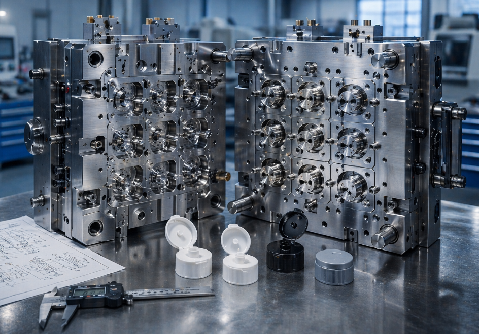
High-performance tooling relies on distinct foundational systems. The hot runner system dictates material distribution. You must choose the right gating approach carefully. Valve gates provide clean entry points and eliminate gate vestige. This clean look is crucial for cosmetic caps used in personal care. Pin-point gates cost less upfront but leave small nubs. You must weigh the cosmetic requirements against the tooling budget.
Rheological balancing in manifolds remains an absolute necessity. Polymer melt experiences different shear rates as it travels. A rheologically balanced manifold ensures identical pressure and temperature for every cavity. This balance prevents short shots in a 16, 32, or 64-cavity configuration. All cavities must fill simultaneously.
Precision steel selection directly affects tool longevity. Industry standards demand premium steel grades for core and cavity blocks. You should expect S136 or H13 steel. Manufacturers must harden these blocks to HRC 48-52. Hardened steel resists aggressive wear from continuous production. It maintains parting line integrity. Tight parting lines prevent flash formation over millions of cycles.
Ejection mechanisms require equal engineering attention. Flip-top caps feature complex undercuts. Standard ejector pins often push too hard on specific areas. This localized pressure causes cap distortion during demolding. Stripper plates offer a much better solution. Stripper plates apply uniform pressure around the entire cap perimeter. They push the part off cleanly. They preserve the delicate hinge structure and the vital sealing rings.
Gating System Evaluation Chart | ||
Feature | Valve Gate System | Pin-Point Gate System |
|---|---|---|
Gate Vestige | Virtually invisible | Noticeable nub present |
Cosmetic Quality | Excellent | Moderate |
Maintenance Complexity | High (requires valve pin care) | Low (fewer moving parts) |
Shear Stress Control | Superior | Average |
The hinge serves as the most critical mechanical component of the cap. Good flow dynamics dictate long-term hinge survival. Your design must force the polymer melt to flow perpendicular to the hinge axis. This specific flow direction aligns the polymer molecules correctly. Typical materials include Polypropylene (PP) or Polyethylene (PE). Correct molecular alignment maximizes flexural strength. It ensures the hinge can withstand hundreds of open-close cycles without tearing.
In-mold closing represents a massive leap in production efficiency. This mechanism folds the cap closed before it fully leaves the tooling. Integrating robotic or mechanical in-mold closing saves significant secondary assembly costs. However, you must carefully evaluate the engineering requirements.
Watch out for several risks when implementing in-mold closing:
Increased Tool Complexity: The mechanism requires specialized sliders and folding racks.
Precise Timing Limits: The folding action must occur while the plastic remains warm and pliable.
Maintenance Overhead: Moving parts within the tool require frequent lubrication and tight tolerance checks.
Post-mold closing provides a highly reliable alternative. Sometimes, accepting a simpler mold design makes better business sense. You can eject the caps in an open state. High-speed downstream capping lines then fold and snap the caps closed. This approach reduces tooling complexity significantly. It lowers your initial capital expenditure. It shifts the mechanical burden from the injection machine to the packaging line.
Optimal cooling design directly correlates to unit cost economics. Injection molding cycles consist mostly of cooling time. Shaving just two seconds off a cycle increases daily output massively. Efficient cooling architecture removes heat rapidly and uniformly. It allows the machine to open faster.
Advanced tooling utilizes conformal cooling channels. Traditional straight-drilled water lines often miss critical hot spots. Conformal channels follow the complex geometry of the cap. You should always look for DFM reports specifying Beryllium copper (BeCu) inserts. Engineers place these BeCu inserts in high-heat concentration areas. Core pins generate immense heat. BeCu conducts heat away far faster than standard tool steel. This rapid heat transfer prevents local overheating and degradation.
Warpage mitigation requires isolated thermal management. The cap body and the flip lid possess different wall thicknesses. They cool at completely different rates. If they share a single cooling circuit, differential shrinkage occurs. Differential shrinkage warps the mating surfaces. A warped lid will never seal correctly. A superior Multi-Cavity Flip-Top Cap Injection Mold incorporates separate cooling circuits. Independent circuits control the body and lid temperatures precisely. This isolation ensures a secure, perfectly aligned, and audible "click" upon closing.
Modern branding often demands distinct visual or tactile features. The market application for 2K (two-color or two-material) molds continues to grow rapidly. Brands frequently require soft TPE/TPR grips. They want distinct color accents. They want these features without paying for secondary assembly operations. 2K injection molding delivers these features simultaneously.
Technical complexity increases exponentially in 2K setups. You must assess the underlying technology. Toolmakers typically use either rotary platen or core-back technology. Rotary platens spin the entire moving half of the tool to inject the second material. Core-back designs use pulling mechanisms to create space for the second shot. You must also evaluate material compatibility risks. Achieving a strong chemical bond between rigid PP and soft elastomers remains difficult. Poor temperature control prevents proper adhesion. The soft grip will peel off in the consumer's hands.
Vendor competence requires intense scrutiny here. Standard mold-makers often claim 2K capability prematurely. Look for immediate red flags. Do they lack a portfolio of successful multi-component tooling? Do they struggle to explain the thermal separation between the two injection barrels? If they cannot demonstrate a deep understanding of multi-shot rheology, walk away. 2K tooling leaves no room for trial and error.
Finding a competent toolmaker requires strict vetting procedures. Do not accept a simple price quote. A credible vendor will provide absolute DFM and Moldflow transparency. They run flow simulation data before cutting any steel. This simulation highlights potential weld lines. It shows where air traps might occur. It maps the stress concentrations along the hinge. You must review these simulations together.
Machining tolerances dictate the final quality of the part. Require proof of high-speed CNC and EDM equipment. Their machinery must hold tolerances within 0.01mm. Loose tolerances create flash and mismatched parting lines. Precision machining ensures perfect cavity interchangeability.
Factory Acceptance Testing (FAT) serves as your final safeguard. Establish non-negotiable trial parameters early in the contract. You must witness the mold running continuously for 4 to 8 hours. This prolonged run proves thermal stability. A tool might run well for twenty minutes but overheat after two hours. Catch these thermal issues before shipping the tool.
Finally, evaluate the warranty and spare parts package. Production will eventually cause wear and tear. Your tooling must include standardized, interchangeable spare parts. Keep extra cores, cavities, and hot runner nozzles on hand. Interchangeability minimizes future maintenance downtime. You can swap a damaged cavity insert directly in the press. You resume production immediately.
Crucial FAT (Factory Acceptance Testing) Parameters | ||
Testing Parameter | Minimum Standard Requirement | Why It Matters |
|---|---|---|
Continuous Run Time | 4 to 8 hours uninterrupted | Proves thermal stability and reveals cooling bottlenecks. |
Dimensional Variance | < 1% across all cavities | Ensures interchangeability on high-speed capping lines. |
Hinge Flex Test | 200+ manual open/close cycles | Validates molecular alignment and hinge fatigue resistance. |
Cycle Time Verification | Must hit quoted target (e.g., 12s) | Confirms the cooling design performs as simulated. |
Investing in a high-quality multi-cavity flip-top cap injection mold is a critical upfront CapEx decision. It directly dictates your long-term operational profitability. Tooling failures create unacceptable downtime and brand damage. A well-engineered tool guarantees high production yields day after day.
Prioritize cooling efficiency: Demand BeCu inserts and conformal channels to hit optimal cycle times.
Protect the hinge: Ensure polymer flow aligns perpendicular to the hinge axis for maximum durability.
Demand precision: Only accept toolmakers capable of holding 0.01mm tolerances across all cavity blocks.
Verify through simulation: Never approve steel cutting without reviewing comprehensive Moldflow and DFM reports.
Your actionable next step is clear. Refuse simple price sheets. Encourage your buying team to request detailed DFM and moldflow analyses when engaging prospective suppliers. Let engineering data guide your vendor selection.
A: The ideal cycle time typically ranges from 10 to 18 seconds. This duration depends heavily on wall thickness, the number of cavities, and cooling efficiency. Thicker caps require longer cooling phases. Utilizing BeCu inserts and conformal cooling channels helps achieve the lower end of this time range.
A: Hinges break due to poor molecular alignment and stress concentrations. A strong mold design forces polymer melt perpendicular to the hinge axis. It uses specific flow leaders. It also avoids placing weld lines anywhere near the bending joint. This maximizes flexural strength and prevents premature tearing.
A: Base your cavity count on machine tonnage limits, expected annual volume, and upfront budget. A 16-cavity tool suits moderate volumes and smaller presses. A 64-cavity tool demands massive injection tonnage and significant capital but delivers extreme high-volume output necessary for global FMCG brands.
A: Yes, material choice heavily impacts design. Polypropylene (PP) and Polyethylene (PE) possess differing shrinkage rates. You must size the cavity dimensions specifically for the chosen resin's shrinkage. Additionally, PP generally requires a slightly different hinge thickness compared to PE to achieve the same optimal flex fatigue life.